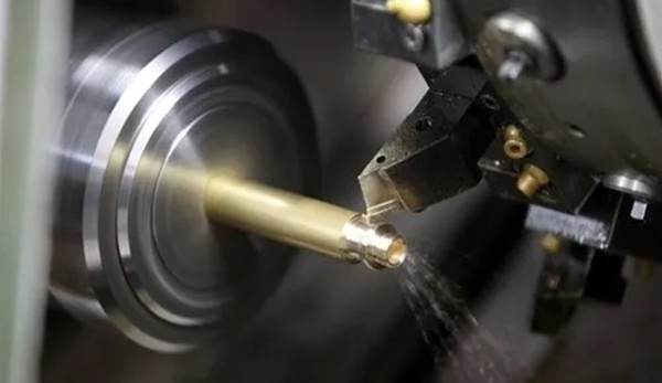
As emerging technology industries continue to develop, the demand for higher product quality is increasing. Mechanical parts are expected to embody the principles of lightweight design and resource efficiency while also emphasizing scientific and practical functionality. Thin-walled parts, with their advantages of being lightweight and having a thin structure, are widely used in the aerospace and modern mechanical engineering fields.
Thin-walled parts are common in CNC turning services and are characterized by their thin walls, low rigidity, and reduced strength. These properties make them prone to deformation during turning, making it challenging to maintain workpiece accuracy. Deformation typically occurs in three forms: clamping deformation, vibration deformation, and thermal deformation, all of which directly affect the workpiece’s dimensional accuracy, shape accuracy, positional accuracy, and surface roughness. For operators, effectively planning the machining process, addressing the challenges of deformation, and efficiently completing the machining of thin-walled parts pose significant challenges.
Common Positioning and Clamping Methods for Thin-Walled Parts
Three-Jaw or Four-Jaw Chuck Clamping: This method is suitable for thin-walled workpieces with short axial dimensions and small radial dimensions. It allows all surfaces of the part that require machining to be processed in a single clamping, reducing the impact of positioning errors on dimensional accuracy.
Chuck and Mandrel Clamping: This method involves separate rough and finish machining processes. First, the workpiece is roughly turned according to the drawing requirements. Next, the outer diameter is clamped in a chuck for precision turning of the internal contour and end face. Finally, an expanding mandrel is used to clamp the internal surface of the workpiece, allowing for the finish turning of the outer diameter and end face.
Faceplate Clamping: Suitable for large-diameter, high-precision thin-walled disk workpieces. The process begins with rough turning, followed by grinding both end faces to meet the required dimensions on a grinding machine. The workpiece is then clamped on a faceplate for precision turning of the inner bore and outer diameter to the specified dimensions.

Clamping Thin-Walled Workpieces on Specialized Fixtures: This method is ideal for batch production of thin-walled parts. Custom tools are designed according to the part’s drawings to ensure efficient and accurate machining.
Choosing Appropriate Tool Geometry and Material
When turning thin-walled workpieces, the cutting tool must be sharp and durable to ensure smooth and efficient machining. The aim is to minimize friction between the tool and workpiece, reducing cutting forces and heat generation. This places high demands on tool geometry and material selection.
- Selection of Tool Geometry:
- A larger primary clearance angle is typically chosen to reduce radial cutting forces and vibration, minimizing deformation.
- A larger secondary clearance angle and relief angle are selected to reduce friction and heat generation.
- Increasing the rake angle appropriately makes the cutting action more effortless.
- A positive cutting edge inclination helps control chip flow direction. When grinding the chip breaker groove, it is essential to maintain consistent groove depth to ensure stable chip evacuation, preventing chip jamming or surface scratches that could affect surface quality.
- A smaller tip radius and minor cutting edge are chosen to reduce vibration.
- Selection of Tool Material:
- For brittle metals like cast iron or cast bronze, tungsten-cobalt carbide tools are recommended.
- For ductile metals such as steel, tungsten-titanium-cobalt carbide or high-speed steel tools are preferred.
- Coated carbide inserts, ceramic inserts, or diamond inserts can also be selected based on machining requirements. Regardless of the material, economic and practical considerations must be balanced, with the ultimate goal of maximizing the tool’s cutting performance to ensure machining quality and efficiency.
Adequate Cooling to Reduce Thermal Deformation

Cutting heat significantly affects the thermal deformation of thin-walled workpieces. It is crucial to apply cutting fluid generously during turning to minimize heat generation and dissipate heat quickly. This effectively reduces the temperature in the cutting zone, extending tool life and improving the quality of the workpiece. For materials where cutting fluid is unsuitable, compressed air can be used for powerful cooling.
Timely Stress Relief to Improve Machining Quality
For thin-walled workpieces that require only one clamping without flipping, clamping force should be high during rough machining. Before finishing, the workpiece should be released to reduce clamping force, allowing internal stresses to be relieved. After re-clamping and aligning the workpiece, machining can continue. Additionally, normalizing heat treatment can be added during the turning process to eliminate internal stresses, reducing deformation and vibration during cutting.
Conclusion
Turning thin-walled workpieces requires a comprehensive understanding of the factors affecting machining deformation. By flexibly applying machining strategies and techniques, selecting appropriate clamping methods, optimizing machining plans, and scientifically planning cutting paths, the quality and efficiency of machining thin-walled workpieces can be significantly improved, whether on conventional lathes or CNC machines.


